Laser Vegetation Imaging Sensor (LVIS)
Laser Vegetation Imaging Sensor (LVIS) :
The Laser Vegetation Imaging Sensor (LVIS) is an airborne laser altimeter. The LVIS mechanical form has been designed to allow it to interface with any aircraft using a standard RC-10 aerial photography camera mount. The LVIS transmitter is a custom diode-pumped laser emitting a 1064-nm wavelength beam. The outgoing laser beam is scanned across the ground marking a swath perpendicular to the aircraft's path.
The light reflected from the ground is collected by an 8-inch (20.3-cm) aperture refractive telescope. A scanning mirror in the receiver tracks the laser beam as it scans across the ground. The LVIS instrument is able to scan a 1.243-mi (2-km) wide swath from an altitude of 40,000 ft (12 km).
Using precision GPS measurements coupled with the on-board inertial navigation unit, LVIS is able to make very high-accuracy range measurements. Perhaps one of the most interesting aspects of LVIS is its ability to directly measure both tree top heights and ground elevation with the same laser pulse.
Challenges:
The LVIS instrument will have a long lifetime. Taking this into account during the design phase required that the solid models be created in a robust fashion. This will ease future improvements and modifications to the design.
Designing LVIS included many packaging challenges. The previous version of the instrument used a custom mount for each aircraft. For this iteration of LVIS, it was desired to use a more common interface. The RC-10 aerial photography camera mount was used since it is quite common. All components must fit inside an 18-inch (45.7-cm) diameter ring to interface with this mount. Various lasers will be used during the lifetime of the instrument.
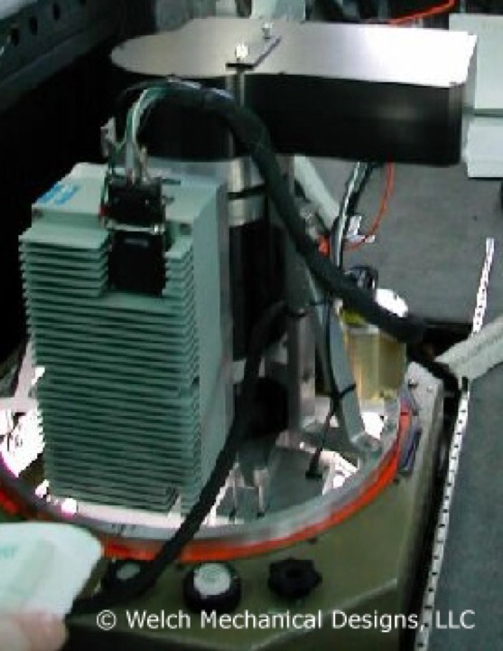
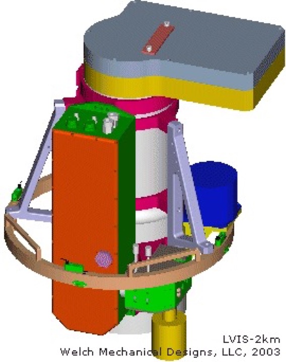
To allow a broad range of adjustments and the ability to replace significant portions of the instrument, the barrel of the receiver was designed to be very strong and rigid. The other components of the instrument clamp to this barrel. To change items, one merely needs to change these clamps and realign the system. The receiver barrel acts as the optical bench providing a highly adaptable platform for mounting the rest of the components in the system. The RC-10 camera mount is attached to the instrument through these clamps as you can see from the photo and rendered image.
Design of the receiver scan mirror previously mentioned required the use of new analysis techniques. Previous versions of the instrument rotated the scan mirror at much higher angular velocities. These high angular velocities required more exotic materials like Beryllium for the mirror substrate. Recent improvements have allowed the receiver scanner to slow to the point where aluminum can now be considered. The shape of the aluminum mirror was optimized with Finite Element Analysis software to have minimum surface distortion under the maximum acceleration while having the lowest rotational mass-moment of inertia. The analysis allowed the mirror design to be optimized prior to fabrication. All of the requirements were met with this design. These mirrors have been machined and the reflective surfaces are single-point diamond machined then over-coated with Quartz to prevent oxidation.
Future:
The next generation of LVIS is currently being designed. This version will have almost twice the field of view. This wider field of view allows a wider scan swath and greatly reduces the number of flight hours required to scan a given area. The next generation design is also smaller so multiple receivers could be used for a combined field of view almost four times the current LVIS.
Related Projects
Aircraft Enclosures